Audi Q7: Control Arm, Removing and Installing
Special tools and workshop equipment required
- Spreader Tool -3424-
- Torque Wrench 1332 40-200Nm -VAG1332-
- Engine and Gearbox Jack -VAS6931-
- Engine/Gearbox Jack Adapter - Wheel Hub Support -T10149-
- Ball Joint Splitter -VAS251805-
Removing
Before starting work:
- Versions with coil springs: determine the curb weight position. Refer to → Chapter "Wheel Bearing in Curb Weight Position, Lifting Vehicles with Coil Spring".
- Vehicles with air suspension: determine the standard vehicle height. Refer to → Chapter "Wheel Bearing at Standard Vehicle Height, Lifting Vehicles with Air Suspension".
- Remove the front wheel. Refer to → Chapter "Wheels and Tires".
- Remove the noise insulations. Refer to → Body Exterior; Rep. Gr.66; Noise Insulation; Noise Insulation, Removing and Installing.
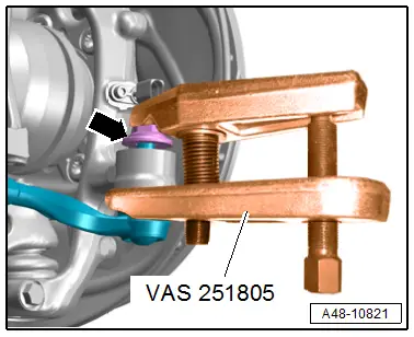
- To protect the threads remove the nut -arrow- on the joint pin tie rod head until it is flush with the threads of the joint pin.
 WARNING
Risk of injury from falling components!
When pressing off, the tie rod end loosens abruptly from the wheel bearing housing. Use, for example, the Engine and Gearbox Jack -VAS6931- to secure.
 Caution
There is a risk of damaging the ball joint puller.
Pay attention that both puller lever arms are parallel to each other when using greatest force.
- Remove the tie rod end with the Ball Joint Splitter -VAS251805- from the wheel bearing housing.
- Remove the nut to do so if necessary counterhold on the joint pin with a 6 mm inner hex socket.
- Tie up the tie rod.
 Note
Note
To prevent the joints on the upper control arm from being damaged, support the wheel bearing housing against too strong rebound.
- Turn the wheel hub, until the wheel bolt hole is on top.
 Caution
Risk of destroying the wheel bearing when installing the wheel bolt.
So that the installed wheel bolt cannot push against the wheel bearing, it (the bolt) must be installed with a washer inserted in between.
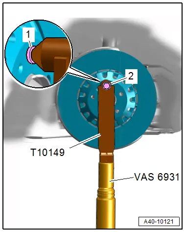
- Install the Engine/Gearbox Jack Adapter - Wheel Hub Support -T10149- with a wheel bolt -2- and inserted washer -1- on the wheel hub.
- Support the wheel bearing housing over the Engine/Gearbox Jack Adapter - Wheel Hub Support -T10149- using the Engine and Gearbox Jack -VAS6931-.
 WARNING
Risk of accident!
- Do not lift or lower the vehicle when the Engine and Gearbox Jack -VAS6931- is under the vehicle.
- Do not leave the Engine and Gearbox Jack -VAS6931- under the vehicle any longer than necessary.
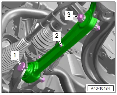
- Remove the nuts -2- and free up the coupling rod for the vehicle level sensor.
- Disconnect the connectors -1 and 3- for the control arm.
- Pivot the control arm toward the front.
 Note
Note
To remove the bolt -1- push the steering all the way to the left or right.
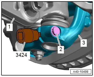
- Remove the bolt -2-.
- Insert the Spreader Tool -3424- in the slit of the wheel bearing housing -3- and turn 90º.
- Remove the control arm -1- with the ball joint.
Installing
Install in reverse order of removal and note the following:
- Bring the control arm with the ball joint into the installation position.
- Install the threaded connections for the components with bonded rubber bushings only until stop but do not yet tighten.
 Note
Note
Bonded rubber bushings have a limited range of motion. Only tighten suspension bolts when vehicle is in curb weight position or at standard vehicle height.
- Lifting the wheel bearing in curb weight position (refer to → Chapter "Wheel Bearing in Curb Weight Position, Lifting Vehicles with Coil Spring") or at standard vehicle height (refer to → Chapter "Wheel Bearing at Standard Vehicle Height, Lifting Vehicles with Air Suspension").
- When tightening the threaded connection -1-, the control arm must be pressed toward the inside of the vehicle.
- Overview table for if an axle alignment is necessary. Refer to → Chapter "Need for Axle Alignment, Evaluating".

Versions with Coil Springs:
- Adjust the headlamps. Refer to → Electrical Equipment; Rep. Gr.94; Headlamps; Headlamp, Adjusting.
- Driver Assistance Systems Front Camera, Calibrating. Refer to → Chapter "Driver Assistance Systems Front Camera, Calibrating".
- Infrared System, Calibrating. Refer to → Chapter "Infrared System, Calibrating".
Versions with Air Suspension:
- Readapt the standard vehicle height. Refer to → Chapter "Standard Vehicle Height, Readapting".
Tightening Specifications
- Refer to → Chapter "Overview - Lower Control Arm and Ball Joint"
- Refer to → Body Exterior; Rep. Gr.66; Noise Insulation; Overview - Noise Insulation.
- Refer to → Chapter "Wheels and Tires"
Guide Link, Removing and Installing
Special tools and workshop equipment required
- Torque Wrench 1332 40-200Nm -VAG1332-
- Torque Wrench 1332 Insert - Ring Wrench - 21mm -VAG1332/7-
- Engine and Gearbox Jack -VAS6931-
- Ball Joint Removal Tool -T10444-
Removing
Before starting work:
- Versions with coil springs: determine the curb weight position. Refer to → Chapter "Wheel Bearing in Curb Weight Position, Lifting Vehicles with Coil Spring".
- Versions with air suspension: determine the standard vehicle height. Refer to → Chapter "Wheel Bearing at Standard Vehicle Height, Lifting Vehicles with Air Suspension".
- Remove the front wheel. Refer to → Chapter "Wheels and Tires".
- Remove the rear noise insulation. Refer to → Body Exterior; Rep. Gr.66; Noise Insulation; Noise Insulation, Removing and Installing.
- Remove the subframe shield. Refer to → Chapter "Subframe Shield, Removing and Installing".
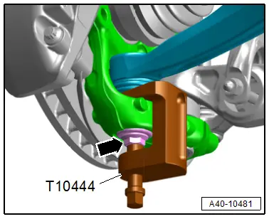
- To protect the threads remove the nut -arrow- on the guide link joint pin until it is flush with the threads of the joint pin.
- Remove the guide link joint pin with the Ball Joint Removal Tool -T10444- from the conical seat, at the same time do not damage the CV boot.
 WARNING
Risk of injury from falling components!
When pressing off, the guide link loosens abruptly from the wheel bearing housing. Use, for example, the Engine and Gearbox Jack -VAS6931- to secure.
- Remove the nut and free up the guide link on the wheel bearing housing to do so if necessary counterhold the joint pin with a TX 40 socket.
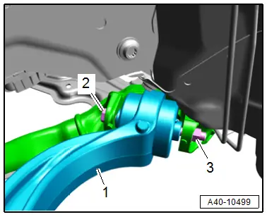
- Remove the nut -3 - and bolt -2-.
- Remove the guide link -1-.
Installing
Install in reverse order of removal and note the following:
- When reusing the guide link clean the pin threads from the remaining locking compound residue
- Install the threaded connections for the components with bonded rubber bushings only until stop but do not yet tighten.
 Note
Note
Bonded rubber bushings have a limited range of motion. Only tighten suspension bolts when vehicle is in curb weight position or at standard vehicle height.
- Lifting the wheel bearing in curb weight position (refer to → Chapter "Wheel Bearing in Curb Weight Position, Lifting Vehicles with Coil Spring") or at standard vehicle height (refer to → Chapter "Wheel Bearing at Standard Vehicle Height, Lifting Vehicles with Air Suspension").
- Overview table for if an axle alignment is necessary. Refer to → Chapter "Need for Axle Alignment, Evaluating".
Tightening Specifications
- Refer to → Chapter "Overview - Lower Control Arm and Ball Joint"
- Refer to → Chapter "Overview - Subframe"
- Refer to → Chapter "Wheels and Tires"

