Audi Q7: Fuel Tank
Overview - Fuel Tank
Overview - Fuel Tank, Market-Specific North America
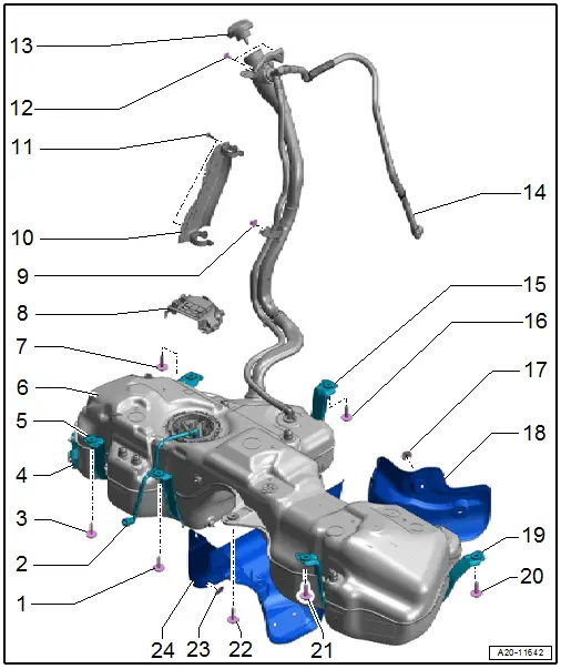
1 - Bolt
- 20 Nm
2 - Fuel Line
- To the engine
- Do not kink
- Clipped to the fuel tank
- Connector couplings, separating and connecting. Refer to → Chapter "Connector Couplings, Disconnecting".
3 - Bolt
- 20 Nm
4 - Fuel Tank Leak Detection Control Module -J909-
5 - Mounting Strap
6 - Fuel Tank
- Refer to → Chapter "Fuel Tank, Removing and Installing".
- Ground connection for discharging electrostatic charge. Refer to → Chapter "Fuel Filler Neck Ground Connection".
7 - Bolt
- 20 Nm
8 - Bracket
- For Fuel Pump Control Module -J538-
9 - Nut
- 2.5 Nm
- To attach the fuel filler neck
10 - Protective Plate
- For the fuel filler neck
11 - Bolt
- 3.5 Nm
- Quantity: 2
12 - Bolt
- 8 Nm
- To attach the fuel filler neck
- Quantity: 2
13 - Cap
- Turn until it clicks into place.
- Attached to the fuel filler door unit with fastener
14 - Bleeder Line
- To the EVAP Canister
- Do not kink
- Connector couplings, separating and connecting. Refer to → Chapter "Connector Couplings, Disconnecting".
15 - Mounting Strap
16 - Bolt
- 20 Nm
17 - Lock Washer
- 0.4 Nm
- For the heat shield
- Quantity: 3
18 - Heat Shield
- For the fuel tank
19 - Mounting Strap
20 - Bolt
- 20 Nm
21 - Bolt
- 20 Nm
22 - Bolt
- 20 Nm
23 - Lock Washer
- 0.4 Nm
- For the heat shield
- Quantity: 7
24 - Heat Shield
- For the fuel tank
Fuel Filler Neck Ground Connection
 WARNING
Danger due to electrostatic charge.
After installing, check the electrical connection on fuel filler neck threaded ring to a bare spot on the body using an ohmmeter.
Specified value: approximately 0 Ω.
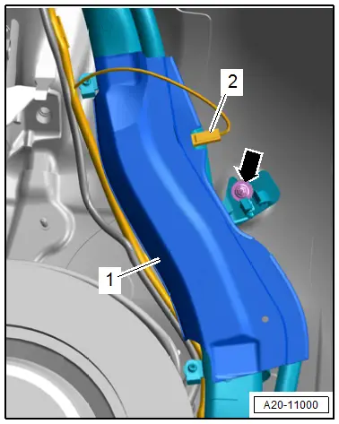
- Route the ground wire as illustrated.
- Make sure the ground wire connector -2- is securely fastened to the metal ring on the fuel filler neck.
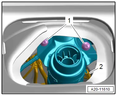
- NAR versions: make sure the ground wire connector -2- is securely fastened to the protective plate -1- for the fuel filler neck.
 Note
Note
Ignore the -arrow-.