Audi Q7: Instrument Panel Vent Motor -V562-, Removing and Installing
The Instrument Panel Vent Motor -V562- is only installed on a vehicle with a "Mix" or "High" A/C system.
 Note
Note
- Depending on vehicle equipment, there are different versions of the A/C system for the Audi Q7. Make sure to use the correct version and pay attention to the allocation of different components. Refer to → Chapter "A/C System Versions" and Parts Catalog.
- Currently in this vehicle, all actuators are identical in construction. During the basic setting, the actuators are assigned and adapted corresponding to the switching sequence of the wiring. If this sequence does not conform with the specification, the actuators will adapt incorrectly and the door control will be wrong. Refer to → Chapter "Main Wiring Diagram for A/C System Actuators".
- Therefore, perform the basic setting for the A/C system after installation of the adjustment motor. Refer to Vehicle Diagnostic Tester in the "Guided Fault Finding" function.
- Using the "output diagnostic test mode" and "basic setting" functions, the activation of A/C system electrical components can be tested if necessary (for example, allocation test). Refer to Vehicle Diagnostic Tester in the "Guided Fault Finding" function.
- After installing a new actuator, check the activation via the Front A/C Display Control Head -E87- and the actuator function. Refer to Vehicle Diagnostic Tester in the "Guided Fault Finding" function.
Removing
- Move the front passenger seat as far back as possible.
- Turn off the ignition.
- Remove the glove compartment. Refer to → Body Interior; Rep. Gr.68; Storage Compartments and Covers; Glove Compartment, Removing and Installing.
- Remove the instrument panel vent on the front passenger side. Refer to → Body Interior; Rep. Gr.70; Instrument Panel; Instrument Panel Vent, Removing and Installing.
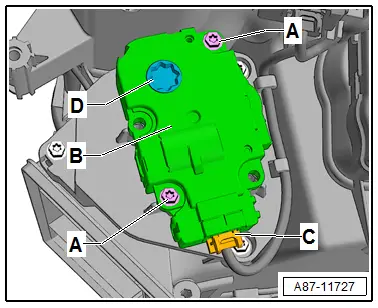
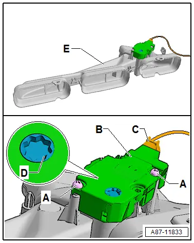
- Remove the air duct -E- (to the center to the right instrument panel vents) -item 7- .
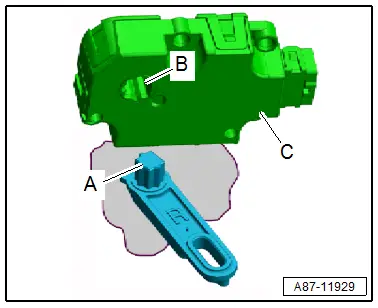
- Remove the bolts -A-.
- Remove the actuator -B- from the door shaft -D-.

Installing
Install in reverse order of removal. Note the following:
 Caution
If the mount -B- for the actuator -C- is turned by hand, then the electronics in the actuator can be damaged.
 Note
Note
The actuator mount does not have a stop. It turns constantly if the actuator is activated. Therefore, this should not be activated with the adjustment motor removed.
- Check the shaft -A- and the mount -B- for the actuator -C-. They must be properly aligned so that they can be joined.
- Attach the actuator mount -B- to the door shaft -A-.
 Note
Note
Check the connection between the actuator mount and the shaft; there must not be any play.

- Tighten the bolts -A-.
- Route the wiring harness to the connector -C- so that it cannot come in contact with any moving parts.
- Install the air duct -E- (to the center to the right instrument panel vents) -item 7-.
- Perform the basic setting and the output diagnostic test mode of the A/C system. Refer to Vehicle Diagnostic Tester in the "Guided Fault Finding" function.
 Note
Note
- In this vehicle, the actuators are equipped with electronics. During the basic setting, a new control motor learns its position on the heater and A/C unit and can then be activated by the Front A/C Display Control Head -E87- (currently all actuators are identical). Refer to Vehicle Diagnostic Tester in the "Guided Fault Finding" function.
- During the basic setting, the actuators are assigned and adapted corresponding to the switching sequence of the wiring. If this sequence does not conform with the specification, the actuators will adapt incorrectly and the door control will be wrong. Refer to → Chapter "Main Wiring Diagram for A/C System Actuators".
- Check the DTC memory on the Front A/C Display Control Head -E87- and erase any displayed malfunctions. Refer to Vehicle Diagnostic Tester in the "Guided Fault Finding" function.
Left Footwell Temperature Control Door Motor -V411-, Removing and Installing
The Left Footwell Temperature Control Door Motor -V411- is only installed on a vehicle with a "Mix" or "High" A/C system.
 Note
Note
- Depending on vehicle equipment, there are different versions of the A/C system for the Audi Q7. Make sure to use the correct version and pay attention to the allocation of different components. Refer to → Chapter "A/C System Versions" and Parts Catalog.
- The Left Footwell Temperature Control Door Motor -V411- and the corresponding doors are only installed on vehicles with a "Mix" or "High" A/C system.
- Currently in this vehicle, all actuators are identical in construction. During the basic setting, the actuators are assigned and adapted corresponding to the switching sequence of the wiring. If this sequence does not conform with the specification, the actuators will adapt incorrectly and the door control will be wrong. Refer to → Chapter "Main Wiring Diagram for A/C System Actuators".
- Therefore, perform the basic setting for the A/C system after installation of the adjustment motor. Refer to Vehicle Diagnostic Tester in the "Guided Fault Finding" function.
- Using the "output diagnostic test mode" and "basic setting" functions, the activation of A/C system electrical components can be tested if necessary (for example, allocation test). Refer to Vehicle Diagnostic Tester in the "Guided Fault Finding" function.
- After installing a new actuator, check the activation via the Front A/C Display Control Head -E87- and the actuator function. Refer to Vehicle Diagnostic Tester in the "Guided Fault Finding" function.
- Refer to → Chapter "Bracket for Left Adjustment Motors, Removing and Installing (on a LowMid A/C System)"
Removing
- Move the driver seat as far back as possible.
- Turn off the ignition.
- Remove the driver side instrument panel cover. Refer to → Body Interior; Rep. Gr.68; Storage Compartments and Covers; Driver Side Instrument Panel Cover, Removing and Installing.
- Remove the left footwell vent (driver side). Refer to → Chapter "Driver Side Footwell Vent, Removing and Installing".
 Caution
A/C system malfunctions in the case of interchanged control motors and/or connectors. Refer to → Chapter "Main Wiring Diagram for A/C System Actuators".
- The adjustment motors and connectors are identical. If they are installed or connected incorrectly, the corresponding doors cannot be properly adapted and/or activated.
- Clearly label the actuators and connectors prior to removal to prevent incorrect installation.
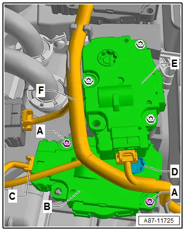
- Remove the Left Footwell Door Motor -V108--E-. Refer to → Chapter "Left Footwell Door Motor -V108-, Removing and Installing".
- Label the connector -C- (to prevent a mix up if several connectors are disconnected at the same time).
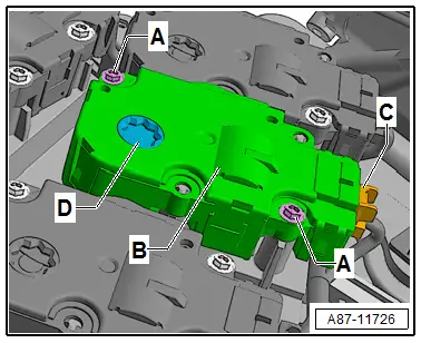
- Remove the bolts -A-.
- Remove the actuator -B- from the door shaft -D-.
- Disconnect the connector -C-.
Installing
Install in reverse order of removal. Note the following:
 Caution
If the mount -B- for the actuator -C- is turned by hand, then the electronics in the actuator can be damaged.
 Note
Note
The actuator mount does not have a stop. It turns constantly if the actuator is activated. Therefore, this should not be activated with the adjustment motor removed.
- Check the shaft -A- and the mount -B- for the actuator -C-. They must be properly aligned so that they can be joined.
- Attach the actuator mount -B- to the door shaft -A-.
 Note
Note
Check the connection between the actuator mount and the shaft; there must not be any play.

- Connect the connector -C- .
- Tighten the bolts -A-.
- Route the wiring harness to the connector -C- and to the other adjustment motors -F- so that it cannot come in contact with any moving parts.
- Perform the basic setting and the output diagnostic test mode of the A/C system. Refer to Vehicle Diagnostic Tester in the "Guided Fault Finding" function.

 Note
Note
- In this vehicle, the actuators are equipped with electronics. During the basic setting, a new control motor learns its position on the heater and A/C unit and can then be activated by the Front A/C Display Control Head -E87- (currently all actuators are identical). Refer to Vehicle Diagnostic Tester in the "Guided Fault Finding" function.
- During the basic setting, the actuators are assigned and adapted corresponding to the switching sequence of the wiring. If this sequence does not conform with the specification, the actuators will adapt incorrectly and the door control will be wrong. Refer to → Chapter "Main Wiring Diagram for A/C System Actuators".
- Check the DTC memory on the Front A/C Display Control Head -E87- and erase any displayed malfunctions. Refer to Vehicle Diagnostic Tester in the "Guided Fault Finding" function.
 Note
Note
- Currently in this vehicle, all actuators are identical in construction. During the basic setting, the actuators are assigned and adapted corresponding to the switching sequence of the wiring. If this sequence does not conform with the specification, the actuators will adapt incorrectly and the door control will be wrong. Refer to → Chapter "Main Wiring Diagram for A/C System Actuators".
- Therefore, perform the basic setting for the A/C system after installation of the adjustment motor. Refer to Vehicle Diagnostic Tester in the "Guided Fault Finding" function.
- Using the "output diagnostic test mode" and "basic setting" functions, the activation of A/C system electrical components can be tested if necessary (for example, allocation test). Refer to Vehicle Diagnostic Tester in the "Guided Fault Finding" function.
- After installing a new actuator, check the activation via the Front A/C Display Control Head -E87- and the actuator function. Refer to Vehicle Diagnostic Tester in the "Guided Fault Finding" function.
- Refer to → Chapter "Bracket for Left Adjustment Motors, Removing and Installing (on a LowMid A/C System)"
Right Footwell Temperature Control Door Motor -V412-, Removing and Installing
The Right Footwell Temperature Control Door Motor -V412- is only installed on a vehicle with a "Mix" or "High" A/C system.
 Note
Note
- The Right Footwell Temperature Control Door Motor -V412- and the corresponding doors are only installed on vehicles with a "Mix" or "High" A/C system.
- Therefore, perform the basic setting for the A/C system after installation of the adjustment motor. Refer to Vehicle Diagnostic Tester in the "Guided Fault Finding" function.
- Using the "output diagnostic test mode" and "basic setting" functions, the activation of A/C system electrical components can be tested if necessary (for example, allocation test). Refer to Vehicle Diagnostic Tester in the "Guided Fault Finding" function.
- Currently in this vehicle, all actuators are identical in construction. During the basic setting, the actuators are assigned and adapted corresponding to the switching sequence of the wiring. If this sequence does not conform with the specification, the actuators will adapt incorrectly and the door control will be wrong. Refer to → Chapter "Main Wiring Diagram for A/C System Actuators".
- After installing a new control motor, check the activation through the Front A/C Display Control Head -E87-, and the function of the actuator (correct position of the recirculation door and the back pressure/fresh air door) . Refer to Vehicle Diagnostic Tester in the "Guided Fault Finding" function.
Removing
- Move the front passenger seat as far back as possible.
- Turn off the ignition.
- Remove the glove compartment. Refer to → Body Interior; Rep. Gr.68; Storage Compartments and Covers; Glove Compartment, Removing and Installing.
- If equipped, remove the air duct for the glove compartment cooling. Refer to → Chapter "Air Guide for Glove Compartment Cooling, Removing and Installing".
- Remove the right footwell vent (front passenger side). Refer to → Chapter "Front Passenger Side Footwell Vent, Removing and Installing".
 Caution
A/C system malfunctions in the case of interchanged control motors and/or connectors. Refer to → Chapter "Main Wiring Diagram for A/C System Actuators".
- The adjustment motors and connectors are identical. If they are installed or connected incorrectly, the corresponding doors cannot be properly adapted and/or activated.
- Clearly label the actuators and connectors prior to removal to prevent incorrect installation.
- Label the connector -C- (to prevent a mix up if several connectors are disconnected at the same time).
- Remove the bolts -A-.
- Remove the actuator -B- from the door shaft -D-.
- Disconnect the connector -C-.
Installing
Install in reverse order of removal. Note the following:
 Caution
If the mount -B- for the actuator -C- is turned by hand, then the electronics in the actuator can be damaged.
 Note
Note
The actuator mount does not have a stop. It turns constantly if the actuator is activated. Therefore, this should not be activated with the adjustment motor removed.
- Check the shaft -A- and the mount -B- for the actuator -C-. They must be properly aligned so that they can be joined.
- Attach the actuator mount -B- to the door shaft -A-.
 Note
Note
Check the connection between the actuator mount and the shaft; there must not be any play.

- Connect the connector -C- .
- Tighten the bolts -A-.
- Route the wiring harness to the connector -C- so that it cannot come in contact with any moving parts.
- Perform the basic setting and the output diagnostic test mode of the A/C system. Refer to Vehicle Diagnostic Tester in the "Guided Fault Finding" function.

 Note
Note
- In this vehicle, the actuators are equipped with electronics. During the basic setting, a new control motor learns its position on the heater and A/C unit and can then be activated by the Front A/C Display Control Head -E87- (currently all actuators are identical). Refer to Vehicle Diagnostic Tester in the "Guided Fault Finding" function.
- During the basic setting, the actuators are assigned and adapted corresponding to the switching sequence of the wiring. If this sequence does not conform with the specification, the actuators will adapt incorrectly and the door control will be wrong. Refer to → Chapter "Main Wiring Diagram for A/C System Actuators".
- Check the DTC memory on the Front A/C Display Control Head -E87- and erase any displayed malfunctions. Refer to Vehicle Diagnostic Tester in the "Guided Fault Finding" function.
Rear Recirculation Door Motor -V421-, Removing and Installing
The Rear Recirculation Door Motor -V421- is only installed on a vehicle with a "Mix" or "High" A/C system.
 Note
Note
- Depending on vehicle equipment, there are different versions of the A/C system for the Audi Q7. Make sure to use the correct version and pay attention to the allocation of different components. Refer to → Chapter "A/C System Versions" and Parts Catalog.
- This adjustment motor is only installed in vehicles with a rear heater and A/C unit (not installed in vehicles with a rear air distribution housing).
- Currently in this vehicle, all actuators are identical in construction. During the basic setting, the actuators are assigned and adapted corresponding to the switching sequence of the wiring. If this sequence does not conform with the specification, the actuators will adapt incorrectly and the door control will be wrong. Refer to → Chapter "Main Wiring Diagram for A/C System Actuators".
- Therefore, perform the basic setting for the A/C system after installation of the adjustment motor. Refer to Vehicle Diagnostic Tester in the "Guided Fault Finding" function.
- Using the "output diagnostic test mode" and "basic setting" functions, the activation of A/C system electrical components can be tested if necessary (for example, allocation test). Refer to Vehicle Diagnostic Tester in the "Guided Fault Finding" function.
- After installing a new control motor, check the activation via the Rear A/C Display Control Head -E265- and the function of the control motor. Refer to Vehicle Diagnostic Testerin the "Guided Fault Finding" function.
- For this adjustment motor to be removed, the entire center console including the base carrier -A- of the center console installed between the base carrier and the rear heater and A/C unit -C- insulation -B- must be removed. Refer to → Body Interior; Rep. Gr.68; Center Console; Overview - Center Console.
Special tools and workshop equipment required
- Strong carpet knife with a point; the blade must be secure and the handle must be strong.
Removing
- Turn off the ignition.
- Remove the base support -A- of center console and insulation -B-. Refer to → Body Interior; Rep. Gr.68; Center Console; Center Console Bracket, Removing and Installing.
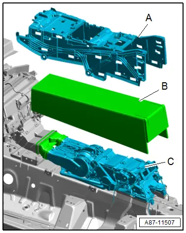
- Using a sharp knife (for example, a strong carpet knife with a point; the blade must be secure and the handle must be strong), disconnect cover grille -A- at indicated connecting points -B- from air ducts -C-.
 Caution
A/C system malfunctions in the case of interchanged control motors and/or connectors. Refer to → Chapter "Main Wiring Diagram for A/C System Actuators".
- The adjustment motors and connectors are identical. If they are installed or connected incorrectly, the corresponding doors cannot be properly adapted and/or activated.
- Clearly label the actuators and connectors prior to removal to prevent incorrect installation.
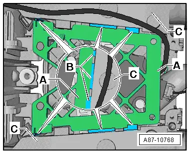
- Label the connector -A- and the actuator -C- (to avoid a mix up in case several connectors are disconnected at the same time).
- Disconnect the connector -A-.
- Remove the bolts -B-.
- Remove the actuator -C- from the relay lever -D-.
Installing
Install in reverse order of removal. Note the following:
 Caution
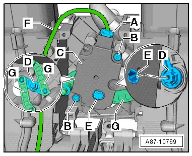
- If the mount -E- from the actuator -C- is turned by hand when the connector -A- is disconnected, the electronics in the actuator can be damaged.
- Only turn the mount -E- of the adjustment motor -C- carefully and slowly with connector -A- connected as far as needed for installation.
 Note
Note
- The mount -E- for the adjustment motor -C- can only be installed in one position on the control lever -D-. If the adjustment motor mount -E- is positioned such that it cannot be joined with actuating arm -D-, the mount in adjustment motor -C- may need to be carefully turned with a suitable screwdriver until the two parts can be joined without force.
- If the mount -E- of adjustment motor -C- is not in the illustrated position (the connecting piece can only be installed in this position), install connector -A- on the adjustment motor and turn the mount of adjustment motor -C- carefully to the position in which the two parts can be joined without pre-tension.
- The mount -E- of adjustment motor -C- does not have a stop. It turns continuously if the adjustment motor is activated. Therefore, this should not be activated with the adjustment motor removed.
- Check actuating arm -D- and the mount -E- of adjustment motor -C-. They must be properly aligned so that they can be joined.
- Ensure that the actuating arm -D- and fasteners -G- are in the correct installation position.
- Install the mount -E- from the adjustment motor -C- on actuating arm -D-.
- Check the connection between adjustment motor -C- and actuating arm -D-. There must be no play.
- Tighten the bolts -B-.
- Connect the connector -A-.
- Install wiring harness -F- so that it cannot come in contact with any moving parts.

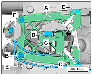
- Attach the cover grille -A- at mounts -D- of air ducts -C--arrow- and secure with bolts -B-. Refer to the Parts Catalog.
- Check the routing of wiring harness -E- to connector -F-. It must not come in contact with any moving components.
- Perform the basic setting and the output diagnostic test mode of the A/C system. Refer to Vehicle Diagnostic Tester in the "Guided Fault Finding" function.
 Note
Note
- In this vehicle, the control motors are equipped with electronics. During the basic setting, a new control motor learns its position on the heater and A/C unit and can then be activated by the Rear A/C Display Control Head -E265- (currently all control motors are identical). Refer to Vehicle Diagnostic Tester in the "Guided Fault Finding" function.
- During the basic setting, the actuators are assigned and adapted corresponding to the switching sequence of the wiring. If this sequence does not conform with the specification, the actuators will adapt incorrectly and the door control will be wrong. Refer to → Chapter "Main Wiring Diagram for A/C System Actuators".
- Check the DTC memory on the Rear A/C Display Control Head -E265- and the Front A/C Display Control Head -E87-) and erase any malfunctions shown. Refer to Vehicle Diagnostic Tester in the "Guided Fault Finding" function.
Rear Air Distribution Door Motor -V427- and Rear Air Quantity Motor -V443-, Removing and Installing
 Note
Note
- Depending on vehicle equipment, there are different versions of the A/C system for the Audi Q7. Make sure to use the correct version and pay attention to the allocation of different components. Refer to → Chapter "A/C System Versions" and Parts Catalog.
- There is a different name for this adjustment motor depending on the version of the A/C system Rear Air Distribution Door Motor -V427- on a "Low" or "Mid" A/C system and a Rear Air Quantity Motor -V443- on a "Mix" or "High" A/C system) in the same component location,
- Therefore, perform the basic setting for the A/C system after installation of the adjustment motor. Refer to Vehicle Diagnostic Tester in the "Guided Fault Finding" function.
- Using the "output diagnostic test mode" and "basic setting" functions, the activation of A/C system electrical components can be tested if necessary (for example, allocation test). Refer to Vehicle Diagnostic Tester in the "Guided Fault Finding" function.
- Currently in this vehicle, all actuators are identical in construction. During the basic setting, the actuators are assigned and adapted corresponding to the switching sequence of the wiring. If this sequence does not conform with the specification, the actuators will adapt incorrectly and the door control will be wrong. Refer to → Chapter "Main Wiring Diagram for A/C System Actuators".
- After installing a new control motor, check the activation through the Front A/C Display Control Head -E87-, and the function of the actuator (correct position of the recirculation door and the back pressure/fresh air door) . Refer to Vehicle Diagnostic Tester in the "Guided Fault Finding" function.
Removing
- Move the front passenger seat as far back as possible.
- Turn off the ignition.
- Remove the glove compartment. Refer to → Body Interior; Rep. Gr.68; Storage Compartments and Covers; Glove Compartment, Removing and Installing.
 Caution
A/C system malfunctions in the case of interchanged control motors and/or connectors. Refer to → Chapter "Main Wiring Diagram for A/C System Actuators".
- The adjustment motors and connectors are identical. If they are installed or connected incorrectly, the corresponding doors cannot be properly adapted and/or activated.
- Clearly label the actuators and connectors prior to removal to prevent incorrect installation.
- Label the connector -C- (to prevent a mix up if several connectors are disconnected at the same time).
- Remove the bolts -A-.
- Remove the actuator -B- from the door shaft -D-.
- Disconnect the connector -C-.
 Note
Note
The illustration shows the installation position on a "Low" or "Mid" A/C system.

Installing
Install in reverse order of removal. Note the following:
 Caution
If the mount -B- for the actuator -C- is turned by hand, then the electronics in the actuator can be damaged.
 Note
Note
The actuator mount does not have a stop. It turns constantly if the actuator is activated. Therefore, this should not be activated with the adjustment motor removed.
- Check the shaft -A- and the mount -B- for the actuator -C-. They must be properly aligned so that they can be joined.
- Attach the actuator mount -B- to the door shaft -A-.
 Note
Note
Check the connection between the actuator mount and the shaft; there must not be any play.
- Connect the connector -C- .
- Tighten the bolts -A-.
- Route the wiring harness to the connector -C- so that it cannot come in contact with any moving parts.
- Perform the basic setting and the output diagnostic test mode of the A/C system. Refer to Vehicle Diagnostic Tester in the "Guided Fault Finding" function.
 Note
Note
- In this vehicle, the actuators are equipped with electronics. During the basic setting, a new control motor learns its position on the heater and A/C unit and can then be activated by the Front A/C Display Control Head -E87- (currently all actuators are identical). Refer to Vehicle Diagnostic Tester in the "Guided Fault Finding" function.
- During the basic setting, the actuators are assigned and adapted corresponding to the switching sequence of the wiring. If this sequence does not conform with the specification, the actuators will adapt incorrectly and the door control will be wrong. Refer to → Chapter "Main Wiring Diagram for A/C System Actuators".
- Check the DTC memory on the Front A/C Display Control Head -E87- and erase any displayed malfunctions using the. Refer to Vehicle Diagnostic Tester in the "Guided Fault Finding" function.