Audi Q7: Steering Column, Checking for Damage
Visual Check
- Components of the steering column must not show any indications of damage.
Function Test
- The steering column must turn without catching or difficulty of movement.
- The steering column must adjust easily from side to side and vertically (this test is only possible when installed).
Steering Column, Handling and Transporting
 WARNING
Safety risk by damaging the steering column.
The correct handling of the steering column must always be observed.
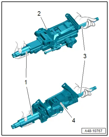
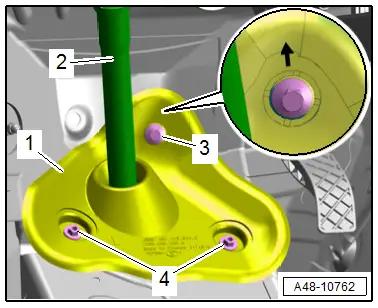
Correct Handling and Transport of Steering Column
2 - Power Steering Column
4 - Manual Steering Column
- Transport steering column using two hands.
- Hold the steering column by the upper outer steering column tube -1- and in the area stub shaft -3- on the upper universal joint.
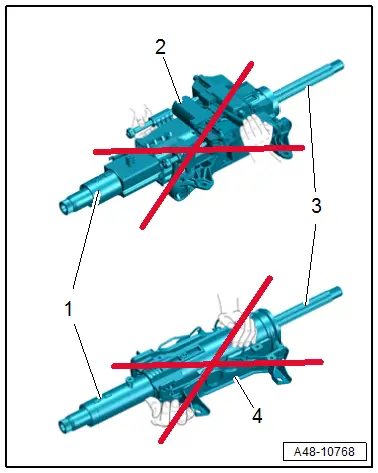
Incorrect Handling of Steering Column
Transporting the following components can cause damage to the steering column and can lead to serious personal injury
- Power steering column -2-: motor, spindles, connectors and wiring harness
- Manual steering column -4-: release lever and weight balancing springs
The steering column must not have any mechanical load:
- A steering column that has fallen onto a hard surface or shows signs of damage must not be installed in the vehicle.
- Do not lay the steering column -1 and 3- on the splines.
- The splines must not get compressed.
Steering Column, Removing and Installing
Special tools and workshop equipment required
- Torque Wrench 1331 5-50Nm -VAG1331-
Removing
- Remove the driver side footwell vent. Refer to → Heating, Ventilation and Air Conditioning; Rep. Gr.87; Air Duct; Driver Side Footwell Vent, Removing and Installing.
- Remove the steering column switch module. Refer to → Electrical Equipment; Rep. Gr.94; Steering Column Switch Module; Steering Column Switch Module, Removing and Installing.
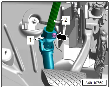
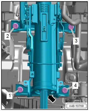
- Remove the bolt -arrow-, and remove the steering intermediate shaft universal joint -1- from the steering column -2-.
- Versions with power steering column: disconnect the connector -arrow-.
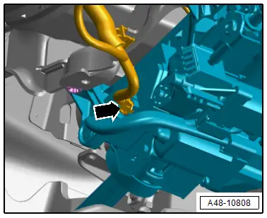
- Remove the bolts in the sequence -4 to 1- at the same time support the steering column -arrow- from below by hand.
- Disengage the steering column from the rear and remove.
 Note
Note
The installation position of the version with a mechanical steering column is shown.
Installing
Install in reverse order of removal and note the following:
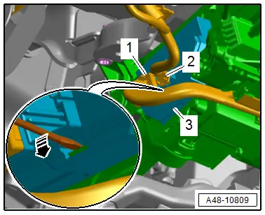
- Bring the steering column into the installation position to do so engage the mounting hooks -1- on the central tube -2--arrow-.
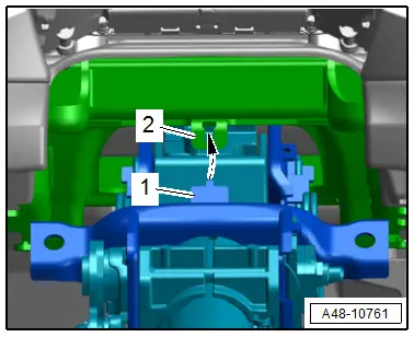
 Note
Note
The installation position of the version with a mechanical steering column is shown.
- Install the bolts loosely and then tighten. Refer to → Fig. "Steering Column - Tightening Specification and Sequence".
- Install the steering intermediate shaft. Refer to → Chapter "Steering Intermediate Shaft, Removing and Installing".
- Readapting the end position of the steering gear. Refer to → Chapter "Steering Gear End Position, Readapting".
- Calibrate the Steering Angle Sensor -G85-. Refer to → Chapter "Steering Angle Sensor -G85- Basic Setting".
- Versions with power steering column: if the steering column is replaced activate the Power Adjustable Steering Column Control Module -J866-. Refer to → Chapter "Power Adjustable Steering Column Control Module -J866-, Removing and Installing".
Tightening Specifications
- Refer to → Chapter "Overview - Steering Column"
Steering Intermediate Shaft, Removing and Installing
Special tools and workshop equipment required
- Torque Wrench 1331 5-50Nm -VAG1331-
Removing
- Bring wheels in the straight position.
- Move the driver seat back to the stop.
- Move the steering wheel as far down as possible to do this use the full steering column adjustment range.
- Switch off the ignition.
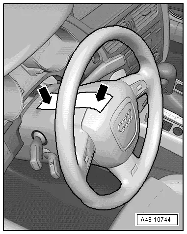
- Secure the steering wheel in the straight-ahead position using adhesive tape so that it does not turn -arrow-.
 Note
Note
- Use adhesive tape, that can be removed without leaving any adhesive residue.
- Be careful not to turn the steering wheel during the repair because the Airbag Spiral Spring/Return Spring with Slip Ring -F138- can become damaged.
- Remove the center noise insulation. Refer to → Body Exterior; Rep. Gr.66; Noise Insulation; Noise Insulation, Removing and Installing.
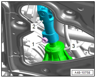
- Remove the bolt -1-.
- Remove the universal joint -2- of the steering intermediate shaft from the steering gear -3-.
- Remove the driver side footwell vent. Refer to → Heating, Ventilation and Air Conditioning; Rep. Gr.87; Air Duct; Driver Side Footwell Vent, Removing and Installing.
- Remove the A-pillar left lower trim panel. Refer to → Body Interior; Rep. Gr.70; Vehicle Interior Trim Panels; A-Pillar Trim Panel, Removing and Installing.
- Remove the accelerator pedal module. Refer to → Rep. Gr.20; Accelerator Mechanism; Accelerator Pedal Position Sensors G79/G185, Removing and Installing
- Push the carpet slightly toward the rear.
- Remove the bolt -3- and nuts -4- and remove the steering intermediate shaft -2- with the sealing lip -1-.
 Note
Note
Ignore the -arrow-.
- Remove the bolt -arrow-, and remove the steering intermediate shaft universal joint -1- from the steering column -2-.

Installing
Install in reverse order of removal and note the following:
 Note
Note
- Replace bolt after removal.
- Clean the threaded hole for the bolt on the universal joint with for example a thread tap.
- Bring the steering intermediate shaft -2- into the installation position at the same time the sealing lip -1- must contact the insulation, as shown.
- The -arrow- points upward.
- Tighten the bolt -3- and nuts -4-.

- Push the intermediate shaft universal joint -2- all the way on the steering column -3-.
- Install the bolt -1- first by hand in the first threads. Check if the steering intermediate shaft is seated correctly by pulling. Tighten the bolt.
- Repeat the procedure on the lower universal joint to the steering gear.
- Readapting the end position of the steering gear. Refer to → Chapter "Steering Gear End Position, Readapting".

Tightening Specifications
- Refer to → Chapter "Overview - Steering Column"
- Refer to → Body Exterior; Rep. Gr.66; Noise Insulation; Overview - Noise Insulation.
- Refer to → Fuel Supply - Gasoline Engines; Rep. Gr.20; Accelerator Mechanism; Overview - Accelerator Pedal Module.
Steering Gear End Position, Readapting
 Note
Note
If the connection between the steering gear and the steering wheel is disconnected, the end position of the steering gear must be readapted.
Special tools and workshop equipment required
- Vehicle Diagnostic Tester
Procedure
- Connect the Vehicle Diagnostic Tester.
- Switch the ignition on.
- Select and start the Diagnostic operating mode.
- Select the Test plan tab.
- Select the button Individual tests and select the following tree structures one after the other:
- Suspension
- Steering
- 01 - OBD-capable systems
- 44 - Power Steering Control Module J500
- 44 - Power Steering Control Module Functions
- 44 - End Position, Readapting
- Start the selected program and follow the instructions in the display of the Vehicle Diagnostic Tester.
Power Adjustable Steering Column Control Module -J866-, Removing and Installing
Removing
- Remove the driver side instrument panel cover. Refer to → Body Interior; Rep. Gr.68; Storage Compartments and Covers; Driver Side Instrument Panel Cover, Removing and Installing.
- Disconnect the connectors -1 and 2-.
- Release the catch in direction of -arrow- and remove the Power Adjustable Steering Column Control Module -J866--3- toward the left.
Installing
Install in reverse order of removal and note the following:
- After installing a new Power Adjustable Steering Column Control Module -J866- activate the control module.
- Connect the Vehicle Diagnostic Tester.
- Switch the ignition on.
- Select and start the Diagnostic operating mode.
- Select the Test plan tab.
- Select the button Individual tests and select the following tree structures one after the other:
- Body
- Electrical system
- 01 - OBD-capable systems
- 09 - Vehicle Electrical Control Module System J519
- 09 - Power Adjustable Steering Column Control Module J866
- J866 Power Adjustable Steering Column Control Module J866 basic setting
- Start the selected program and follow the instructions in the display of the Vehicle Diagnostic Tester.

