Audi Q7: Suspension Strut, Removing and Installing
- Torque Wrench 1331 5-50Nm -VAG1331-
- Torque Wrench 1783 - 2-10Nm -VAG1783- for versions with air suspension.
- Torque Wrench 1783 - Open Jaw - 10mm -VAG1783/1- for versions with air suspension.
Removing
- Remove the shock absorber fork. Refer to → Chapter "Shock Absorber Fork, Removing and Installing".
- Remove the additional reinforcement for the tower brace. Refer to → Chapter "Tower Brace Additional Reinforcement, Removing and Installing, Q7 without High-Voltage System".
Versions with Air Suspension:
 Note
Note
- Follow the guidelines for clean working conditions. Refer to → Chapter "Guidelines for Clean Working Conditions".
- Make sure that during the assembly work that no pressure points are created on the air suspension boot.
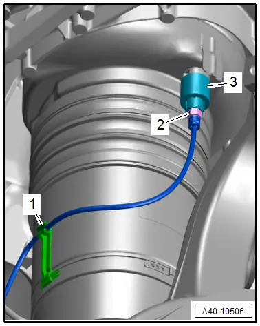
- Remove the air line -2- on the residual pressure valve -3-. Air escapes then.
- Free up the air line -1- on the bracket.
 Note
Note
The residual pressure valve cannot be removed separately.
- Seal both connections.
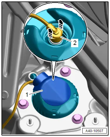
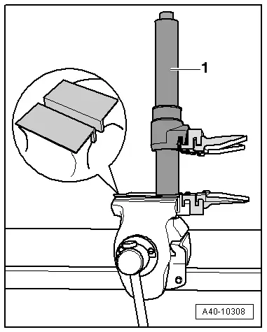
- Remove the cover -1-.
- Disconnect the connector to do so release the locking ring -2- upward in direction of -arrows-, remove the connector.
Continuation for All Vehicles:
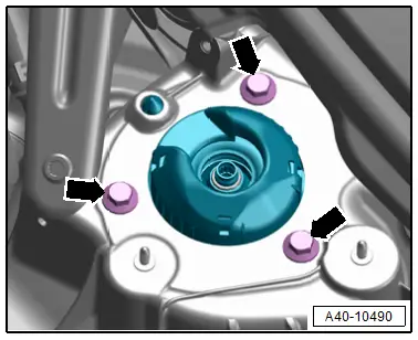
- Remove the bolts -arrows-, remove the suspension strut at the same time do not damage the CV boot on the steering and the drive axle as well as the boot.
Installing
Install in reverse order of removal and note the following:
 Note
Note
Procedures when installing a new air spring. Refer to → Chapter "Suspension Strut, Filling".
- Pay attention to the installation position:
- Refer to → Fig. "Suspension Strut Coil Spring Installation Position"
- Refer to → Fig. "Coil Spring Cap Installation Position"
- Refer to → Fig. "Installation Position Air Spring Suspension Strut"
- Refer to → Fig. "Air Spring Cap Installation Position"
Versions with Coil Springs after Replacing the Springs:
- Adjust the headlamps. Refer to → Electrical Equipment; Rep. Gr.94; Headlamps; Headlamp, Adjusting.
- Driver Assistance Systems Front Camera, Calibrating. Refer to → Chapter "Driver Assistance Systems Front Camera, Calibrating".
- Infrared System, Calibrating. Refer to → Chapter "Infrared System, Calibrating".
Versions with Air Suspension:
- Air suspension system, filling. Refer to → Chapter "Air Suspension System, Filling and Bleeding".
- Readapt the standard vehicle height. Refer to → Chapter "Standard Vehicle Height, Readapting".
Tightening Specifications
- Refer to → Chapter "Overview - Suspension Strut and Upper Control Arm"
- Refer to → Chapter "Overview - Lower Control Arm and Ball Joint"
Suspension Strut, Servicing
Special tools and workshop equipment required
- Torque Wrench 1332 40-200Nm -VAG1332-
- Spring Compressor Kit -VAG1752-
- Spring Compressor Kit - Spring Retainer w/Inserts -VAG1752/6-
- Shock Absorber Set -T10001-
 Note
Note
Because of different shock absorber valve systems, only install new shock absorbers from the same manufacturer on both axles, if possible.
Coil Spring, Removing
- Tension the Spring Compressor Kit - Spring Tensioner -VAG1752/1--1- in a vise with jaw protectors.
- Tension the coil spring shock absorber in the Spring Compressor Kit - Spring Tensioner -VAG1752/1--1- as shown.
- Pretension the coil spring in the spring compressor kit - spring tensioner until the upper spring plate with the spring support are free.
- Remove nut from the piston rod.
- Remove individual components of suspension strut and coil spring with the spring compressor kit - spring tensioner.
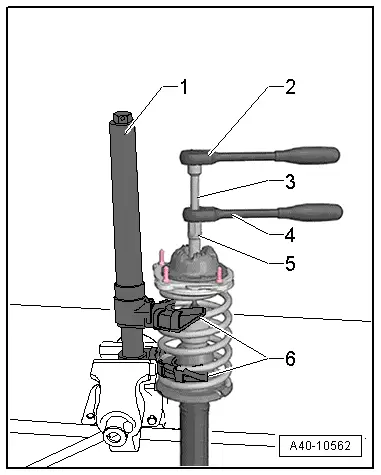
1 - Spring Compressor Kit - Spring Tensioner -VAG1752/1-
2 - Ratchet, commercially available
3 - Shock Absorber Set - Extension SW6 -T10001/7-
4 - Shock Absorber Set - Reversible Ratchet -T10001/11-
5 - Shock Absorber Set - Socket -T10001/3-
6 - Spring Compressor Kit - Spring Retainer w/Inserts -VAG1752/6-
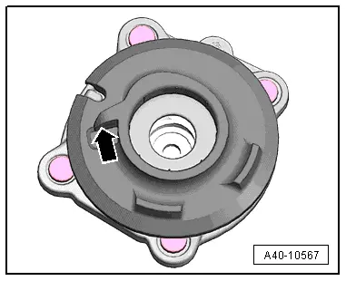
- Pay attention that the coil spring in the Spring Compressor Kit - Spring Retainer w/Inserts -VAG1752/6- is seated correctly -arrow-.
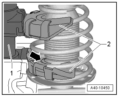
1 - Spring Compressor Kit - Spring Tensioner -VAG1752/1-
2 - Spring Compressor Kit - Spring Retainer w/Inserts -VAG1752/6-
Replacing the Shock Absorber
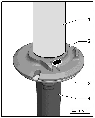
- Remove the cap -1- and the lower spring support -2-.
- Loosen suspension strut -3- using plastic hammer and remove upward from the shock absorber -4-.
Coil Spring, Installing
- Install the spring plate -3- onto the new shock absorber -4- using a rubber hammer.
- Position the lower spring seat -2- and the protective cap -1-.
- Position the pretensioned coil spring on the lower spring support. End of spring coil must rest against stop -arrow- (permissible play max. 2 mm).
- Position individual suspension strut components.

- Position the upper spring plate with the spring support on the pretensioned spring so that the spring supports rests against the end of the coil spring -arrow-.
- Permitted maximum play 2 mm.
- Install the shock absorber mounting.
- Tighten the new nut using special tools -item 6-
- Release the tension from the Spring Compressor Kit - Spring Tensioner -VAG1752/1- and remove.
 Note
Note
Make sure the ends of the spring in the upper and lower spring plates are touching the stops on the spring supports when releasing the tension on the spring compressor.