Audi Q7: Shock Absorber, Removing and Installing
Special tools and workshop equipment required
- Torque Wrench 1331 5-50Nm -VAG1331-
- Torque Wrench 1332 40-200Nm -VAG1332-
- Engine and Gearbox Jack -VAS6931-
- Engine/Gearbox Jack Adapter - Wheel Hub Support -T10149-
 Note
Note
Because of different shock absorber valve systems, only install new shock absorbers from the same manufacturer on both axles, if possible.
Removing
Before starting work:
- Versions with coil springs: determine the curb weight position. Refer to → Chapter "Wheel Bearing in Curb Weight Position, Lifting Vehicles with Coil Spring".
- Versions with air suspension: determine the standard vehicle height. Refer to → Chapter "Wheel Bearing at Standard Vehicle Height, Lifting Vehicles with Air Suspension".
- Remove the rear wheel. Refer to → Chapter "Wheels and Tires".
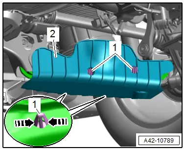
- Release the catches in direction of -arrows- and remove the locking pin -1- slightly.
- Remove the wind deflector -2- in the rear area downward from the transverse link.
- Unlock the catches again and remove the locking pin and the wind deflector.
- Turn the wheel hub, until the wheel bolt hole is on top.
 Caution
Risk of destroying the wheel bearing when installing the wheel bolt.
So that the installed wheel bolt cannot push against the wheel bearing, it (the bolt) must be installed with a washer inserted in between.
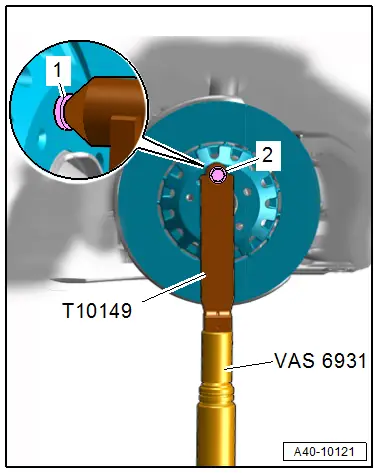
- Install the Engine/Gearbox Jack Adapter - Wheel Hub Support -T10149- with a wheel bolt -2- and inserted washer -1- on the wheel hub.
- Insert the Engine/Gearbox Jack Adapter - Wheel Hub Support -T10149- in the Engine and Gearbox Jack -VAS6931- and lift the wheel bearing housing slightly.
 WARNING
Risk of accident!
- Do not lower the wheel bearing housing with the engine and transmission jack if the upper or lower threaded connection for the shock absorber was separated.
- Do not leave the engine and gearbox jack under the vehicle any longer than necessary.
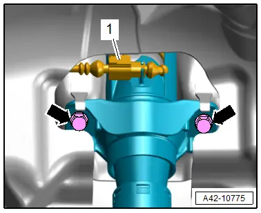
- Disconnect the connector -1-, if equipped.
- Remove the bolts -arrows- on the upper shock absorber fastener.
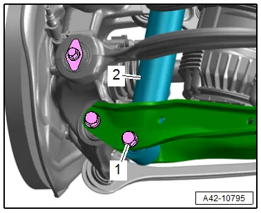
- Disconnect the connector -1- and remove the coil spring -2-.
Installing
Install in reverse order of removal and note the following:
- Install the threaded connections only until stop but do not yet tighten.
 Note
Note
Bonded rubber bushings have a limited range of motion. Only tighten suspension bolts when vehicle is in curb weight position or at standard vehicle height.
- Lifting the wheel bearing in curb weight position (refer to → Chapter "Wheel Bearing in Curb Weight Position, Lifting Vehicles with Coil Spring") or at standard vehicle height (refer to → Chapter "Wheel Bearing at Standard Vehicle Height, Lifting Vehicles with Air Suspension").
- Overview table for if an axle alignment is necessary. Refer to → Chapter "Need for Axle Alignment, Evaluating".
Tightening Specifications
- Refer to → Chapter "Overview - Wheel Bearing"
- Refer to → Chapter "Wheels and Tires"
Shock Absorber, Servicing
Special tools and workshop equipment required
- Torque Wrench 1332 40-200Nm -VAG1332-
- Shock Absorber Set -T10001-
Loosening and tightening the nut
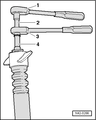
1 - Ratchet (commercially available)
2 - Shock Absorber Set - Extension with Counter Holder 1 -T10001/9-
3 - Shock Absorber Set - Reversible Ratchet -T10001/11-
4 - Shock Absorber Set - Socket -T10001/1-

